

 Lietuva


onsemi Pairing Gate Drivers Infographic
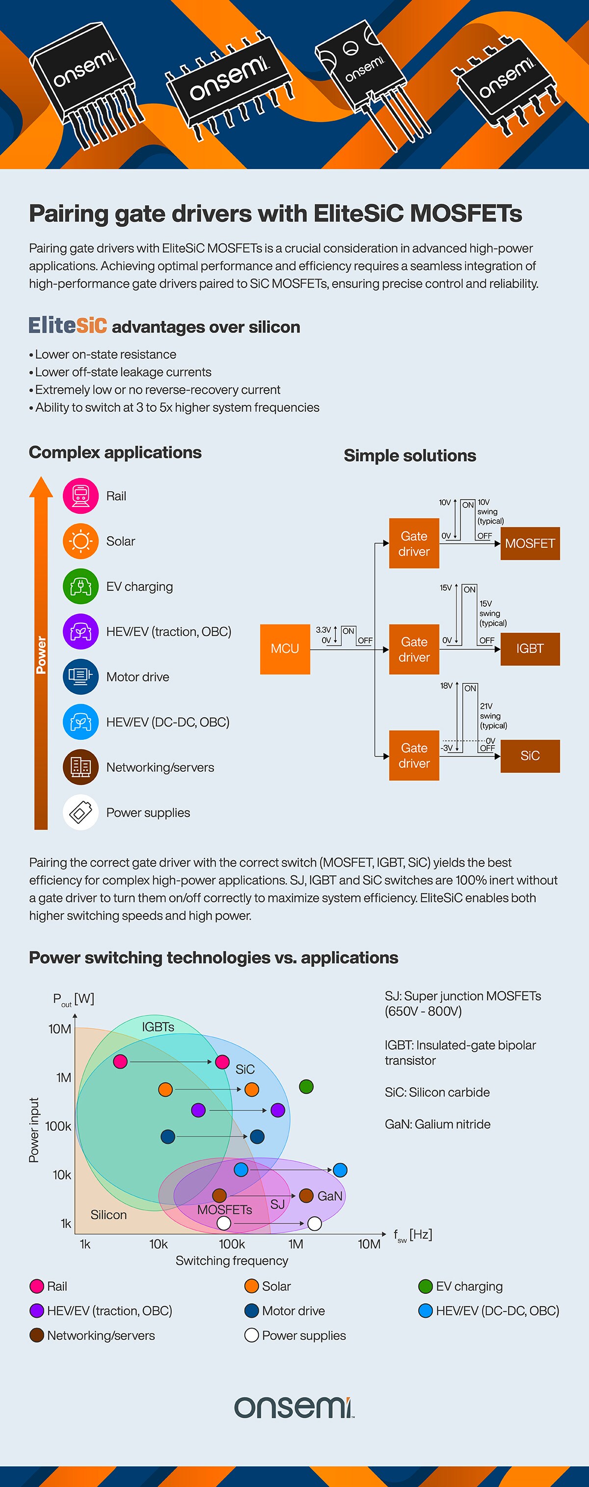
Top Graphic shows onsemi EliteSiC MOSFETs on an abstract background.
Heading: Pairing Gate Drivers with EliteSiC MOSFETs
Text under heading:Pairing gate drivers with EliteSiC MOSFETs is a crucial consideration in advanced high-power applications. Achieving optimal performance and efficiency requires a seamless integration of high-performance gate drivers paired to SiC MOSFETs, ensuring precise control and reliability.
Subhead: EliteSiC advantages over silicon
- Lower on-state resistance
- Lower off-state leakage currents
- Extremely low or no reverse-recovery current
- Ability to switch at 3 to 5x higher system frequencies
Left subhead: Complex applications
Graphic with application icons beneath with power arrow ascending from lower to higher:
Icons in order from lower to higher:
Power supplies shown with battery icon in white circle
Networking/servers shown with server icon in brown circle
HEV/EV (DC-DC, OBC) shown with green energy eco car icon in light blue circle
Motor drive with motor icon in dark blue circle
HEV/EV (traction, OBC) shown with green energy eco car icon in purple circle
EV charging shown with plug car icon in green circle
Solar shown with sun icon in orange circle
Rail shown with train icon in pink circle
Right subhead: Simple solutions
Shown block diagram with ON/OFF voltage shown:
MCU 0V – 3.3V paired to gate driver 0V – 10V to a MOSFET
MCU 0V to 3.3V paired to gate driver 0V – 15V to an IGBT
MCU 0V to 3.3V paired to gate driver -3V – 18V to a SiC MOSFET
Supporting text below block diagram: Pairing the correct gate driver with the correct switch (MOSFET, IGBT, SiC) yields the best efficiency for complex high-power applications. SJ, IGBT and SiC switches are 100% inert without a gate drive to turn them on/off correctly to maximize system efficiency. EliteSiC enables both higher switching speeds and high power.
Subhead: Power switching technologies vs. applications
Venn diagram displaying 1k to 10k, 100k, 1M and 10M increments Power Input on Y axis and Switching Frequency on X axis.
Side legend:
SJ: Super junction MOSFETs (650V – 800V)
IGBT: Insulated-gate bipolar transistor
SiC: Silicon carbide
GaN: Galium nitride
- Silicon – spans 1k up to 10M Pout [W] & between 1k and over 100k fSW [Hz] range
- MOSFETs – spans 1k to 10k Pout [W] & approx. 12k to 1M fSW [Hz] range
- SJ – spans 1k to 10k Pout [W] & approx. 12k to 1M fSW [Hz] range
- IGBT – spans approx. 5k to over 10M Pout [W] & 1k to 100k fSW [Hz] range
- SiC – spans 5k to 10M Pout [W] & 1k to 1M fSW [Hz] range
- GaN – spans 1k to 10k Pout [W] & 12k to nearly 10M fSW [Hz] range
- Rail – falls slightly over 1M Pout [W] and spans 1k to 100k fSW [Hz] range
- Solar – falls slightly below 1M Pout [W] and just past the 100k fSW [Hz] range
- EV charging – falls slightly below 1M Pout [W] and 1M fSW [Hz] range
- HEV/EV (traction, OBC) – sits slightly up 100k 1M Pout [W] and spans the 10k to 1M fSW [Hz] range
- Motor drive – sits slightly below the 100k 1M Pout [W] and spans the 10k to under 1M fSW [Hz] range
- HEV/EV (DC-DC, OBC) – falls on 10k Pout [W] and spans 100k to nearing 10M fSW [Hz] range
- Networking/servers – sits slightly over 1k and spans 100k to 1M fSW [Hz] range
- Power supplies – falls on 1k Pout [W] and spans 100k to over 1M fSW [Hz] range
Bottom: onsemi logo