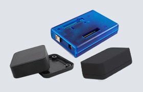
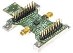
ADPA1106-EVALZ

Analog Devices
584-ADPA1106-EVALZ
ADPA1106-EVALZ

Gam.:

Aprašymas:
RD kūrimo priemonės ADPA1106 Eval Board

Prieinamumas

Turime sandėlyje:
Ne Sandėlyje Esantys
Gamintojo numatytas pristatymo laikas
10 Savaičių Apytikriai apskaičiuotas gamybos laikas gamykloje.
Min. 1   Užsakoma po 1
Vieneto kaina:
-,-- €
Plėt. Kaina:
-,-- €
Numatomas Įkainis:
Šis Produktas Siunčiamas NEMOKAMAI

Kainodara (EUR)

Qty. Vieneto kaina
Plėt. Kaina
1 105,51 € 1 105,51 €

Produkto Požymis Atributo vertė Pasirinkite Požymį
Analog Devices Inc.
Gaminio kategorija: RD kūrimo priemonės
RoHS:  
Evaluation Boards
RF Amplifier
ADPA1106
2.7 GHz to 3.5 GHz
Prekės Ženklas: Analog Devices
Aprašymas/Funkcija: Evaluating the ADPA1106 46 dBm (40 W), 2.7 GHz to 3.5 GHz, GaN Power Amplifier
Skirta naudoti su: GaN Power Amplifier
Darbinė Maitinimo Įtampa: 50 V
Pakavimas: Bulk
Gaminio tipas: RF Development Tools
Serija: ADPA1106
Gamyklinės pakuotės kiekis: 1
Subkategorija: Development Tools
Rasta produktų:
Norėdami rodyti panašius produktus, pažymėkite bent vieną langelį
Pasirinkite bent vieną žymimąjį langelį, kad būtų rodomi panašūs šios kategorijos produktai.
Pasirinkti atributai: 0

TARIC:
8543900000
CAHTS:
8543900000
USHTS:
8543906800
JPHTS:
854390000
MXHTS:
8543900100
ECCN:
EAR99

EVAL-ADPA1106 Evaluation Board

Analog Devices Inc. EVAL-ADPA1106 Evaluation Board evaluates the ADPA1106 GaN Power Amplifier. The board consists of a 2-layer printed circuit board (PCB) fabricated from a 10-mil thick, Rogers 4350B copper-clad mounted to an aluminum heat spreader. The heat spreader assists in providing thermal relief to the device and as mechanical support to the PCB. Mounting holes on the heat spreader allow the spreader to be attached to a heat sink. Alternatively, the spreader is clamped to a hot and cold plate. The RFIN and RFOUT ports on the ADPA1106-EVALZ are populated by Subminiature Version A (SMA) female coaxial connectors, and the respective RF traces have a 50 Ω characteristic impedance. The ADPA1106-EVALZ is populated with components suitable for use over the entire operating temperature range of the device. To calibrate board trace losses, a through calibration path is provided between the J6 and J5 connectors. J6 and J5 must be populated with SMA RF connectors to use them through calibration path.